Differences Between LMI and RCL
Differences Between LMI and RCL
A telehandler Load Management System (LMS) is one that includes an LMI, an RCL or both.
– Longitudinal Moment Indicator (LMI) – Measures the weight applied on the rear tyres. As the weight on the tyres decreases the LMI increases.
– Rated Capacity Limiter (RCL) – Measures the weight of the lifted load and compares it against the maximum rated load for the current boom angle and boom length.
Below is a more detailed description of an LMI and an RCL.
LMI
LMI stands for Longitudinal Moment Indicator. The longitudinal moment is when the centre of gravity of the telehandler moves forward enough to tip the machine over the front end with the rear tyres off the ground. The LMI works by measuring the force applied by the rear tyres on the ground. This is typically done by measuring the twisting force on the rear axle using a strain gauge attached to the axle itself. As the radius of the boom increases (either by extending or lowering the boom) force on the rear axle decreases and the LMI value increases.
A typical LMI uses a number of sequential lights to warn the operator when approaching the longitudinal tipping moment. The lights start off green, then change to orange and red as the longitudinal tipping moment approaches. When all the lights on the LMI indicator are lit (100% capacity) any further increases in radius will cause the telehandler to tip forward.
Usually the LMI is connected into an aggravated movement hydraulic cutout, which prevents extending and lowering of the boom if the telehandler is about to tip forward.
The LMI will decrease or increase when traversing up or down a hill respectively. This is due to the shift in the centre of gravity as the angle of the carrier changes.
The LMI will increase with any boom movement that increases the radius, even if the telehandler is not lifting any load, which is different from the way an RCL performs.
RCL
RCL stands for Rated Capacity Limiter. An RCL, such as the GEN3-LMS (Generation 3 Load Management System), measures the weight of the load and compares it against the manufacturer recommended load rating for the current boom angle and length extension and whether the stabilisers are raised or lowered.
In the GEN3-LMS, the weight of the load is measured using pressure sensors installed in the main lift cylinder. As the weight of the load is increased, the pressure of the hydraulic oil in the lift cylinder also increases.
The rating chart is generated from the manufacturer’s recommendations and testing performed during the machine’s design. It is programmed and stored within the GEN3-LMS in an electronic format.
To determine the location within the rating chart, a cable reeler is used to measure the boom length and an inclinometer is used to measure the boom angle. The software converts the length and angle into radius and height to match the rating chart.
The RCL indicates the capacity to the operator via a percentage bar. This bar shows the percentage of the lifted load compared to the maximum rated load from the rating chart. If the lifted load exceeds 100% a hydraulic cutout is enabled similar to an LMI, preventing any further increases in radius.
If the telehandler is not lifting any load, the percentage bar will show 0% and will not increase if the radius or boom length is increased.
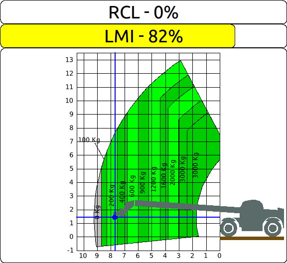
Boom extended almost to maximum at a low boom angle with no load attached.
The LMI is at 82% capacity while the RCL is still at 0%.
Why an RCL is Required for Suspended Load Attachments
There are two variates of attachments for telehandlers; fixed load and suspended load attachments. Fixed load attachments anchor the load directly to the attachment, such as forks or buckets. Suspended load attachments are connected to the load via cable, such as jibs or winches.
Suspended load attachments can cause the load to swing in all directions. If the load swings in a lateral direction as the boom is raised higher this can cause the telehandler to tip over side. An LMI can only warn the operator of longitudinal swing and not lateral swing.
The rating chart for a suspended load attachment derates the load as the boom travels higher, reducing the risk of tipping sideways due to lateral swing. The RCL enforces the rating charts preventing the operator from lifting a load that could tip the telehandler sideways due to lateral swing.
Why an LMI is Better When Working on a Steep Down Slope
When operating on a steep down slope, the LMI will more than likely warn the operator when about to tip forward before the RCL does. This is due to the two different load measurement systems. However, for the LMI to warn before the RCL, means the operating slope is steeper than is allowed by the manufacturer and further operation should not be attempted.
Cost Differences Between LMI and RCL Systems
A typical LMI system uses a single sensor mounted on the rear axle connected into a display mounted in the cabin. The display unit processes the sensor information and displays this to the operator.
A typical RCL system uses a number of sensors mounted on the boom to measure the load. It also uses separate sensors to measure the boom angle and boom length. All the sensor data is processed and is shown on the display.
As an RCL system requires more sensors and processing, it is more expensive than an LMI system. However, considering issues mentioned above, an RCL system is typically more reliable, accurate and safer than an LMI.